Debugging the Printrbot assembly process
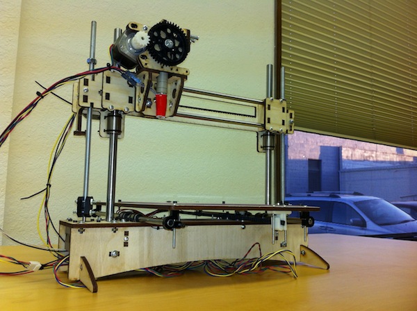
I had a few troubles assembling the Printrbot+, but overall it was a very enjoyable process! Imagine a robotic power tool that you get to build yourself out of a lovely wooden Erector Set — in the end the challenges below were all just part of the fun.
Base assembly
It took a couple tries to get the base assembly together "right side up" so that the USB and SD slots on the electronics board lined up with the right slots in the panel. Just as when woodworking you "measure twice, cut once" the solution to this is simply to "test fit twice, carpal tunnel once": not only do you need to make sure the arrows are all pointing to the front, you need to make sure the whole base isn't also inside out by making sure the Printrboard will work underneath before you put in too many screws.
Missing parts
Brook and Co include a handful of extra fasteners so for the most part I was able to make do.
The most major missing parts were the z-axis bearings, which they happily made right. (The original mistake was due to quality issues with a third-party shipper, and they've resolved that too by bringing things back in-house.)
I was also missing a sufficiently long smaller black bolt, and corresponding standoff, for the odd fourth corner hole of the Revision B electronics board. It seemed sturdy enough with only three tie points and so I'm just doing without.
By the time I got to the end, I was running out of the mid-length screw sizes. I had plenty of loooooong ones though and so I was able to hacksaw/file off the excess lengths in each place and finish the job. For the z-axis clamps, even the mid-sized bolts were just slightly too long and would gouge into the wooden bridge as it went past. Rather than trim a few threads off I just added two washers per bolt on the head side of each, so I could tighten the joint properly without the bolt's nether end getting too long.
Broken extruder, beta extruder
The original plastic extruder sent with the earlier kits was badly cracked when I unboxed it and positively broken by the time I'd finished trying to assemble it.
Along with the missing bearings, Printrbot HQ graciously sent me a Wooden Extruder Kit to try. Much much much better! (At this point in the assembly process, I started wondering if I shouldn't have been pining after a laser cutter instead of a plastics printer :-)
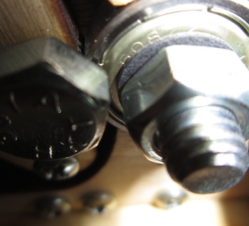
I still had two issues with it though: the bolt hob no longer lined up with the filament slot, and furthermore as it spun the nut on the end tended to self-tighten until it had bound the whole mechanism up. I got stuck waiting to hear back from HQ with any ideas, but the fixes turned out to be simple after talking the problem through with a coworking space friend:
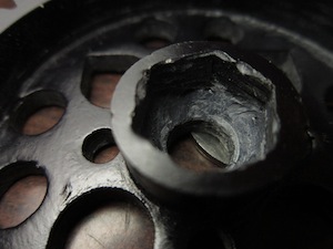
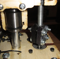
The original gear hub had plenty of depth available to get a good start on shifting the bolt hob closer to its target. Even my messy(/dangerous) bit of "hold the part in one hand and the drill in the other" routing got the job done well enough. Once my printing and modeling skills increase I should be able to fix it properly with a custom fitted one!
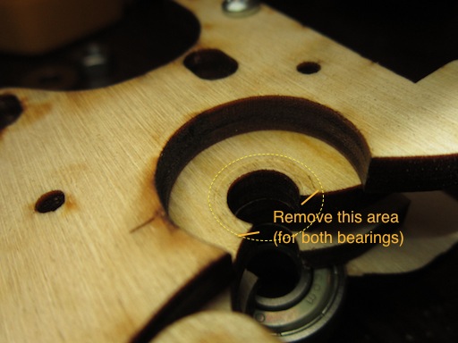
The self-tightening problem was primarily do to a self-reinforcing nasty feedback loop with the bearings. When tightened down, the inside rolling part would start catching on the wood, which meant the nut couldn't roll along with the bolt as well, which meant it tightened down…. This part would have been easier with a drill press too, but I simply used a knife to carve away a channel for the inner bearing piece. By giving it some empty space, it can continue to roll freely as the static bearing body clamps down.
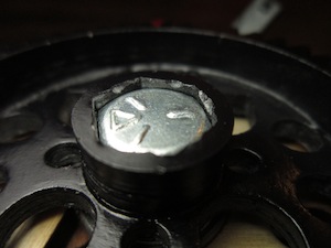
Finally, switching out the kit's fat metal washers for some sleek "fiber washers" I picked up at Home Depot served two purposes: not only did it stop a lingering self-tightening problem when the bigger washer would bind on the pinch roller part, but it also finished fixing the filament alignment problem.
Note that I also had to take out some of the screws and turn them in from the opposite side instead (versus what the store's pictures of the assembled extruder show), so that they wouldn't interfere while the thin washer lets the gear ride so much closer to the assembly.
Cable management
I still don't really have this solved, but it works I guess.
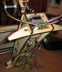
Seeing all the wooden parts work together so brilliantly, I was a bit surprised when I got to wiring everything up to the board. Cable management seems like a total afterthought — most cables are way too long, some are a bit too short, and there's really not a whole lot provided in the way of guidance holes or tie points.
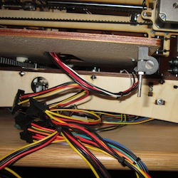
My general strategy was to ziptie cables together where they would naturally "bundle" For example, there's three separate wires from the extruder that all need to end up at the board. So I lined them up, tugging gently on the ends as I ran my hand towards the extruder, tightening them together until I got to where they needed to go their separate ways. That spot got a zip tie, and then back down towards the board every so often to turn it into one thick cable. Similarly for the bed wires, the x-axis cables sets, etc. Basically, you want one nice bundle in place of wherever there were two or three sets of two or four wires each twisting all over.
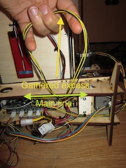
Under the bot, the other trick that kind of worked was to make a loop of the "slack part" of extra cabling, so that at the bottom of the loop the rest of the line was a nice slug length. I then ziptied that line at the bottom of the loop, leaving two parts: the "main" cable run in place, plus a somewhat more manageable single loop I could sort of sweep under the rug with all the others.
I still ended up with kind of a mess, especially after adding the power supply which comes with its own nest of cables. I'll probably get the Power Tower to help with that (as well as the other Printrbot nesting material: the filament tangle!) at some point. It's messy to see cables pushing out underneath the stand, but so long as they don't catch on the underside of the bed as the y-axis moves, it's not a particularly urgent problem either.
Gathering the heated bed
It's possible to print directly (well, I assume there'd still be tape on top) onto the included heating plate. However, I was getting pretty proud of what I'd built (well, at least assembled) and wanted to finish it right; according to the discussions online, that meant getting a plate of glass and insulating the flat heated surface from the wooden bed.
I wanted to keep it simple, too, so as not to deviate too far from the Printrbot LC "birch and bolts" aesthetics. I started from this post as well as another encouraging using simple binder clips on the glass, stopped by an Ace Hardware just up the road from Room to Think, and here's what I came up with:
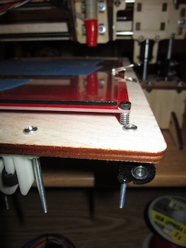
Basically just two needed springs chopped in half, holding the four corners against the screw head above and the nut beneath. I didn't bond the nuts underneath like the forum post — screws not glue™ — a socket wrench will work just fine if I need to adjust more later.
This was actually one of the funnest parts. Doing a bit of research, and then deciding how I wanted to set up my particular printer, and gathering the parts needed to make it happen— it's one feeling to have something "just work" when it's fresh out of a shiny box, it's quite another to realize that picking up some springs and struts at a hardware store will never be out of warranty. With that being said,
Missing instructions
…there are a lot of good resources for getting this thing built — not the least of which is engaging the creative "DIY" side of one's brain! — but going to http://printrbot.com/instructions/ as your starting place is (currently) not one of them. The PDF there is great for getting started after assembly, but (especially for the Printrbot+ specifically) I'd recommend starting with Craig the Fabricator's better-paced assembly videos, moving on to the wiki instructions when those run out, then falling back to your inner maker spirit and the forums as you tie up all the loose ends. At least, that's what seems to have worked for me ;-)

Locking yourself in a garage until you emerge with a made-from-scratch homebrew CNC exruder a month or two later has been the rite of passage in the original RepRap community. So having to find some better step-by-step assembly videos ALL BY MYSELF was kind of a pansy problem. But I still hope that Brook and Co continue polish up the experience, making it almost (though perhaps intentionally not quite) completely "plug-and-play". The hardware itself is 99% of the way there, basically just plus/minus a few fasteners and a bit better base plate labeling. All it's missing is a booklet that goes from step 1 to step 97 with instructions specific to the pieces in the box, reviewed and user tested to find any lingering pitfalls, and I really think their "your first 3d printer" could be assembled by just about anyone in just a few evenings!
Of course… assembly's just the first part…